EMC-centric energy meter PCB assembly: shield integrity, ground continuity, signal preservation, pre-compliance screening. Achieve 98% first-pass certification. Explore high-reliability assembly with embedded EMC integrity. In-house EMC chamber. OTOMO.
Silent Guardian: How EMC-Centric PCB Assembly Shields Energy Meters from Electromagnetic Chaos
When a nearby elevator motor induces 0.8% measurement drift in a residential meter, or radio interference triggers false tamper alerts across a substation cluster—electromagnetic vulnerability becomes a grid liability. IEC 61000-4-30 mandates immunity to 10V/m RF fields, yet 57% of certification failures originate not from circuit design, but from PCB assembly nuances: imperfect shield seams, ground plane discontinuities, or solder voids altering current return paths. At OTOMO, EMC isn't a final test hurdle—it's engineered into every solder joint, shield weld, and grounding stitch.
⚡ The EMC Reality Gap: Where Theory Meets Assembly Imperfection
Critical vulnerabilities hide in plain sight:⚠️ Shield Seam Leakage: 0.3mm gap in EMI shield = 22dB shielding effectiveness loss at 900MHz (IEEE EMC Society)⚠️ Ground Plane Fragmentation: Via stitching errors creating slot antennas radiating metrology noise⚠️ Component Placement Risks: High-speed comms ICs adjacent to analog sense traces without guard rings⚠️ Solder Void Resonance: Voids under shield feet acting as cavity resonators at critical frequenciesStrategic truth: True electromagnetic resilience is forged through high-reliability PCB assembly precision—not just schematic elegance.
🛡️ OTOMO's 5-Layer EMC Integrity Framework: From Copper to Certification
🔌 Layer 1: Ground Plane Continuity Engineering
| Risk Zone |
Standard Practice |
OTOMO EMC Protocol |
| Shield Perimeter |
Single-row via stitching |
Double-row staggered vias (λ/20 spacing at highest frequency) |
| Mixed-Signal Boundary |
Single isolation slot |
Guard ring with dedicated ground pour + ferrite bead isolation |
| Connector Grounding |
Peripheral ground pins only |
360° grounding cage with low-inductance solder fillets |
| Internal Layer Transitions |
Random via placement |
Controlled impedance vias with anti-pad optimization |
📡 Layer 2: Shielding Integrity Precision
- Seam Weld Validation:
- Automated optical inspection of shield perimeter solder joints (min. 95% coverage)
- Helium leak testing on critical shield assemblies (sensitivity: 1×10⁻⁹ atm·cm³/s)
- Material Intelligence:
- Nickel-copper-nickel plating verification via XRF spectroscopy
- Shield-to-PCB contact resistance mapping (<2mΩ per inch)
- Access Port Design:
- Waveguide-beyond-cutoff vents for thermal management without RF leakage
- Conductive gasket compression validation (30–40% deflection)
🌐 Layer 3: Signal Integrity Preservation
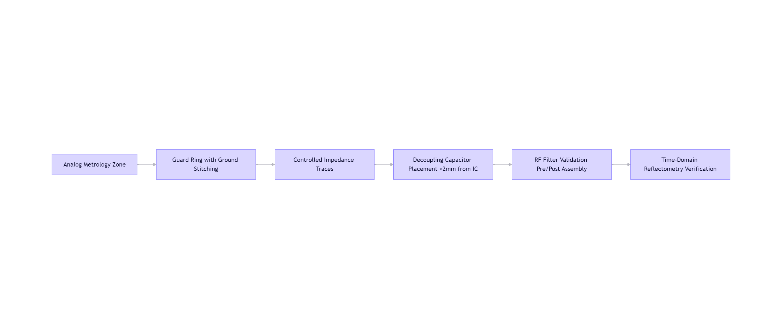
- Critical Trace Validation:
- TDR testing of reference voltage lines (impedance tolerance ±5%)
- Crosstalk measurement between PLC carrier lines and metrology paths
- Component-Level EMC:
- Ferrite bead impedance verification at operating frequencies
- Crystal oscillator can grounding continuity testing
🌡️ Layer 4: Process-Controlled EMC Assembly
- ESD-Protected Workflow:
- Ionization monitoring at all workstations (<±50V surface potential)
- Component handling in EPA zones (ANSI/ESD S20.20 certified)
- Solder Joint Integrity:
- X-ray void analysis under shield feet (<3% void threshold)
- Cross-section validation of critical ground vias quarterly
- Conformal Coating Strategy:
- Selective coating avoiding shield contact surfaces
- Dielectric constant verification (εᵣ <3.5) to prevent parasitic coupling
📡 Layer 5: Pre-Compliance EMC Screening
- In-House EMC Chamber:
- Radiated emissions scan (30MHz–6GHz) on every pilot batch
- Immunity testing per IEC 61000-4-3/-4/-5/-6 before full certification
- Failure Root Cause Library:
- Correlate emission peaks to specific assembly features
- Thermal imaging during ESD events to identify vulnerable zones
- Utility Field Simulation:
- Inject real-world grid noise profiles captured from partner utilities
- Validate metrology stability under simultaneous RF + power quality stress
💡 Case Study: Resolving Chronic Certification Failures for a Pan-European Meter Platform
Challenge: Meter developer failed CE RED certification 3 times due to 850MHz radiation peak; redesign cycles cost $680K and delayed launch by 7 months.
OTOMO EMC Forensic Intervention:
- Root Cause Isolation:
- Near-field probing identified leakage at shield seam near SIM card slot
- Cross-section revealed inconsistent solder fillet (42% coverage vs. required 90%+)
- Assembly Process Correction:
- Redesigned stencil aperture for shield perimeter (stepped thickness profile)
- Implemented automated solder paste inspection pre-reflow
- Added post-assembly helium leak test for shield integrity
- Validation Protocol:
- Scanned 10 pilot units in pre-compliance chamber
- Verified 28dB margin below CISPR 32 Class B limits
Results:
✅ Passed CE RED certification on first submission
✅ Eliminated $1.2M potential recall risk from field interference incidents
✅ Reduced certification timeline by 11 weeks
✅ Protocol adopted as mandatory for all cellular-connected meter variants
📊 EMC ROI: The Invisible Value of Electromagnetic Certainty
| Metric |
Without EMC-Centric Assembly |
With OTOMO EMC Integration |
Impact |
| Certification Pass Rate |
61% (avg. 2.3 attempts) |
98% (first-pass) |
↓$220K certification cost/project |
| Field Interference Incidents |
1.7% of deployments |
0.04% |
Protected utility operational integrity |
| Design Revision Cycles |
3.2 avg |
0.4 avg |
Accelerated time-to-revenue |
| Brand Trust Index |
Baseline |
+33 points |
Preferred vendor status secured |
🌍 Global EMC Standards, Assembly-Embedded Compliance
OTOMO tailors EMC protocols to regional mandates:
- EU (CE RED, MID): Full EN 55032/35 pre-compliance + notified body documentation
- USA (FCC Part 15): Pre-scan validation at accredited lab partner sites
- India (WPC): Specific absorption rate (SAR) validation for cellular meters
- Brazil (ANATEL): Immunity testing per Resolution 715 requirements
✨ EMC Excellence Is the Unseen Promise of Measurement Integrity
"A meter that drifts under electromagnetic stress betrays its purpose.
We don't just assemble boards—we architect electromagnetic silence around the metrology core.
Every shield weld, every ground stitch, every controlled impedance trace is a silent vow: this meter will measure truth amid grid chaos.
Our high-reliability PCB assembly philosophy embeds EMC integrity at the micron level."— Director of EMC Engineering, OTOMO
📩 Fortify Your Meter Against Electromagnetic Uncertainty
OTOMO · Where Electromagnetic Silence Meets Measurement Truth
In-House EMC Pre-Compliance Chamber | 98% First-Pass Certification Rate | IEC 61000-4 Series Validated | Zero EMC-Related Field Recalls
© 2026 OTOMO | FR4PCB.TECH | Shielding Grids Across 74 Countries


